CLM configuration management: Defining your component strategy
Nick Crossley, Persistent Systems
Last updated: 13 November 2017
Build basis: IBM Collaborative Lifecycle Management Solution (CLM) 6.0.4 and higher, IBM IoT Continuous Engineering (CE) Solution 6.0.4 and higher
This article is part of a series that provides guidance for planning configuration management for the IoT CE solution.
Introduction
Components typically represent physical or logical subdivisions of your product or system. A component consists of some set of artifacts. In CLM, a Rational DOORS Next Generation component could contain requirement artifacts, such as features and glossary terms; an Rational Team Concert (RTC) component contains a set of directories and files; and an Rational Quality Manager component could contain test artifacts, such as plans, test cases, and test results. Thus, component terminology differs slightly depending on the application:
In Global Configuration Management (GCM), and the requirements (RM) and quality management (QM) applications, each configuration – a baseline or stream – is a configuration of one component.
In RTC source control management (SCM) and Rhapsody Model Manager:
- A stream is a configuration of a set of components
- A component baseline captures the frozen configuration of one or more components
- A snapshot is a frozen configuration of a stream, containing component baselines
In CLM version 6.0, GCM introduced the ability to define global components to represent aggregate building blocks in your product or system, and to use components as the basis of configuration management.
CLM version 6.0.3 introduced components smaller than project areas in RM and QM, so one project area can contain multiple components; RTC SCM and GCM already supported this finer-grained component structure. Completing the picture in 6.0.5, Rhapsody Model Manager uses the same configuration management system as RTC SCM, and so also provides fine-grained components.
Since components form the unit of configuration management, it is important to have an appropriate set of components; this article discusses approaches to determine how you partition your artifacts between components.
In this article, the following application names stand for these products:
- RM = Requirements Management — local configurations managed by Rational DOORS Next Generation
- DM = Design Management — local configurations managed by Rational Design Manager
- AM = Architecture Management — local configurations managed by Rhapsody Model Manager
- QM = Quality Management — local configurations managed by Rational Quality Manager
- CCM = Change and Configuration Management — code streams managed by RTC SCM
- GCM = Global Configuration Management — global configuration application
- RELM = Rational Engineering Lifecycle Manager — views of product engineering data
- JRS = Jazz Reporting Service — for real-time charts and reports from CLM data
- RPE = Rational Publishing Engine — for document-style reports
Criteria for component boundaries
Reuse: If a group of artifacts is reused in different products, or in different ways or places in the same product or its variants, you can use different configurations of those artifacts to manage this reuse. That set of artifacts should be grouped into one component. Conversely, if two groups of artifacts need to be reused in different combinations at the same time, you want to put those two groups in different components.
For example, if a part has a power supply and a diagnostic display panel, and another part has the same diagnostic display panel but a different power supply, the requirements for the power supply should be in one component and the requirements for the display panel should be in a different component.
Similarly, a software organization might build and maintain several systems that reuse common components, such as (1) a family of services that deal with user security and (2) a software component for a custom spreadsheet widget. These capabilities would most likely be defined, constructed, and tested by different teams. To facilitate the independent reuse of the capabilities, their lifecycle artifacts could be managed using separate components.
Development and delivery schedule: If two groups of artifacts are developed independently on different schedules – quite possibly by different teams in different locations – it makes sense to divide those artifacts into different components. This approach allows the teams to use different configurations that can be baselined according to their different schedules.
Usability and performance: You might want to separate artifacts into multiple components to improve these factors. Consult your IBM team for the appropriate sizing guidelines for the maximum number of artifacts in a component
- The collection of artifacts is intended for reuse in more than one context.
Example: an engine control unit (ECU) that is used in both a truck and an SUV. - The collection of artifacts is delivered to another party as a separate delivery.
Example: a radio component delivered to a team working on the luxury model of a car and also to a third-party vendor of satellite technology. - The collection of artifacts is delivered by a separate team or on a different cadence.
Example: the stakeholder requirements need to be baselined before the system or functional requirements. - The collection of artifacts has a separate delivery cycle.
Example: a database consistency and repair tool might be shipped separately from the primary product that owns the database. - The number of artifacts would be too large to manage in a single component.
Of course, you must weigh these considerations against the increased complexity of adding more components. Too many components impairs usability. Furthermore, some practical limitations in version 6 releases suggest that you should use a single component for a group of artifacts in some CLM applications:
- Consider using a single RM component for requirements that share the same set of type definitions.
Although you can use component templates and import type definitions to manage shared types across a set of components, that approach increases the cost of maintenance, which you must weigh against the advantages of using separate components, as previously discussed. - Use a single QM component for all the test plans that share any of the same test cases, test scripts, test environments, and so on, as well as those test artifacts themselves.
You can separate the artifacts for one or more test plans but clone the shared artifacts to parallel versions in each component, however, this is not recommended. Such parallel versions become difficult to maintain, and you might need to migrate them to separate components in the future. - In both RM and QM, you can only view artifacts from a single component at a time in a single view. You can use different views in different browser tabs or windows, but you might consider keeping artifacts in the same component if you always want to view those artifacts together in the application interface. Note that you can bring together information from multiple components in JRS and RPE reports, and in RELM views.
In current CLM releases, you can’t put configurations of two or more RM components that share any of the same artifacts into a single global configuration. This situation could easily happen when you reorganize your requirements into components. That is, if requirement #15 appears in component R1 (for some versions of requirement #15), and also exists in component R2 (for some different versions of requirement #15), you cannot add any configuration of component R1 to a global configuration that already contains a configuration of R2, and vice versa. This constraint might also apply to QM in future releases.
So, for a group of requirements that need to be used together in a single global configuration, you have two choices:
- Keep the requirements in one component.
- Split them into separate components but don’t continue cloning them between components in use.
How you group artifacts into components might be similar across applications if you follow a simple mapping from physical components. For example, if you group all the requirements for one circuit board in an A/V receiver into one RM component, you might group all the test cases for that circuit board into one QM component. However, this is not necessary; based on some of the preceding criteria, you might decide to group your test plans for the receiver by the type of test, or by the test team responsible for running the test.
Components vs. configurations
A component is typically very long lived and represents a conceptual unit. A configuration represents a set of artifacts of that component that are grouped for a specific purpose, such as a specific release, version, or variant of the component, or an insulated working environment, or a shared integration stream.
Avoid creating new components when a new configuration of the same component is more appropriate, because this can make it harder to find configurations and harder to ensure consistency across multiple global configurations.
Global vs. local components
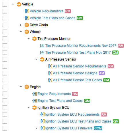
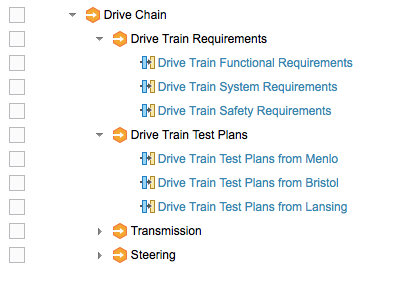
In a typical product composition structure, each global component is mirrored by at least one local component in each of the applications in use. For example, if you have a global component for the engine subsystem of a vehicle, that engine component probably also has requirements, test plans, firmware source code, and so on. Often, each application has more than one local component – for instance, the engine requirements might be subdivided into separate components for user requirements, system requirements, non-functional requirements, safety requirements, and so on. This approach allows you to develop configurations of those components on independent schedules, and to reuse baselines of those components appropriately.

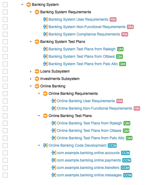
This approach applies to each level of the configuration hierarchy, not just the leaves. So, while each ECU in an engine has its requirements, test plans, firmware source code, and so on, the engine as a whole is likely to have its own requirements, test plans, and so on. Configurations of these higher-level requirements and other items might appear directly as contributions to configurations of the global component, as shown in the example above, or they might appear indirectly through configurations of global components that group the requirements separately from the test plans. That is, with fine-grained component structures in RM and QM, you might have a global component whose configurations group together just a set of requirement components, and another global component whose configurations group together just test components.
or, with a software-oriented example:

Component organization
In themselves, components in GCM, RM, and QM are flat – they have no built-in structure or hierarchy. Instead, structure is built using configuration hierarchies in the GCM application, as shown in the earlier pictures.
Nonetheless, sometimes you want to organize your components into something other than a flat list. Organization is especially important if you have very large numbers of components.
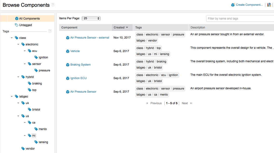
You can organize global components by tagging them. Each tag is a string. A global component can have any number of tags. You can set up your own tagging conventions to define multiple independent organizations. For example, you might have one set of tags to classify components according to some government or industry part classification scheme, another set of tags to define the reuse capability of the components, and a third set of tags to indicate the ownership or origin of the components. With tags, you can find global components quickly and easily. From there, you can find configurations of those components.
CLM 6.0.4 introduced the ability to visualize your global component organization as a hierarchy using tags. The tagged view uses the forward slash character (/) to form a logical hierarchy of tag names. For example, the electronic/sensor/pressure tag might indicate a part classification scheme, and the us/ca/menlo tag might indicate a component designed or developed in your Menlo facility.
Because you can use multiple independent tags, consider using the first part of each tag string as an identifier of the classification scheme. The previous tags would be better as class/electronic/sensor/pressure and labgeo/us/ca/menlo.

Summary
Components make it easier to reuse and work with parts of a product or system. Component and stream strategy go hand-in-hand: you can’t finish one without the other. Read more about defining the configurations and stream patterns for the local and global components in the next article in this series: Patterns for stream usage.
Organize your artifacts into components to mirror your product building blocks, to reflect your product or team organizational structure, to maximize your opportunities for reuse, and to allow independent development by separate teams.
Avoid creating new components when creating simple variants of existing parts. Use configurations of the same component to differentiate variants.
Use tags to make it easy to find components and their configurations quickly, and to visualize component organization and structure in different ways.
For more information
Contact Tim Feeney at tfeeney@us.ibm.com or Kathryn Fryer at fryerk@ca.ibm.com.
See the following topics in IBM Knowledge Center:
- Activating configuration management in the RM and QM applications
- Using components in the RM and QM applications
- Creating components in the GCM application
About the author
Nick Crossley is a Senior Technical Staff Member at Persistent Systems, responsible for the architecture of product line engineering, version and variant management, configuration management, and cross-domain baselining in the CLM solution. Nick leads the OSLC standardization work on Configuration Management, and has over 40 years of experience with software tools and development. He can be contacted at nicholas_crossley@persistent.com.
© Copyright IBM Corporation 2017