
How we use CLM to build CLM
Overview
The Rational solution for Collaborative Lifecycle Management (CLM) is a set of seamlessly integrated Jazz based tools that work together as one: IBM Rational Team Concert, IBM Rational Quality Manager, IBM Rational Requirement Composer and now Rational Design Manager. The tools that make up the CLM solution have always self-hosted with the development teams using the tools themselves to develop the tools, but the tools have historically each been run as independent projects with their own code, test, requirements, and design repositories. Beginning in 2009 with the initial CLM integrations between Rational Team Concert V2 and Rational Quality Manager V2, we faced the challenge of how to develop tight integrations between tools that are created by different development teams. We could have attempted to merge the development teams together, but that is disruptive, and extremely large development teams are not typically very efficient. Since the purpose of the CLM solution is to provide integration within development toolsets, we turned to our old friend, self-hosting, as the way to approach the problem. We created best practices for using the CLM integrations themselves to coordinate development across a large multi-project team. This article will discuss the approach we created and refined with the hope that it will help others that face similar challenges.
To create an integrated project structure for the CLM solution, we created a higher-level umbrella project area as the integration vehicle between the existing project areas at show in figure 1. This structure initially included the existing Jazz Foundation, Rational Team Concert, and Rational Quality Manager projects. Rational Requirements Composer was added in 2010, and Rational Design Manager in 2011.
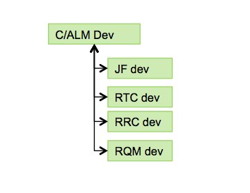
Figure 1. CLM Project Structure
The CLM project area is primarily a wrapper project for coordinating the governance of the overall CLM solution. It serves as the entry point for anyone that wants information about the overall solution and serves as the index and cross-reference for the solution. It includes the overall development plan and backlog for CLM level features, and host’s defect and enhancement workitems that pertain to the solution as a whole. It also includes CLM dashboards to track status and progress of the overall solution.
Linkage from the CLM project area to the other projects is provided by the Open Services for Lifecycle Collaboration (OSLC) based integration capabilities implemented in the CLM solution. This provides for a rich set of web style linkages between various types of lifecycle artifacts such as:
- Project to Project
- Plan to Plan
- Related Change Requests
- Change Request to Test Case
- Requirement to Test Case
- Requirement to Change Request
- Defect to Test Case
- Defect to Change Request
Development Rhythm
In addition to linking the projects together, we also had to deal with the issue of the development rhythm between the various teams. We chose to synchronize the iteration schedules between the teams. This required agreeing on a common approach to planning, development, and stabilization activities within iterations. It also meant adopting common processes for end of iteration demos, sign-off, deployment to self-host, retrospectives, and the creation of new and noteworthy documentation. Our approach is shown in figure 2. We have experimented with both 3 and 4 week iteration cycles and are now using 4 week cycles as a good compromise between being responsive and iteration overhead.
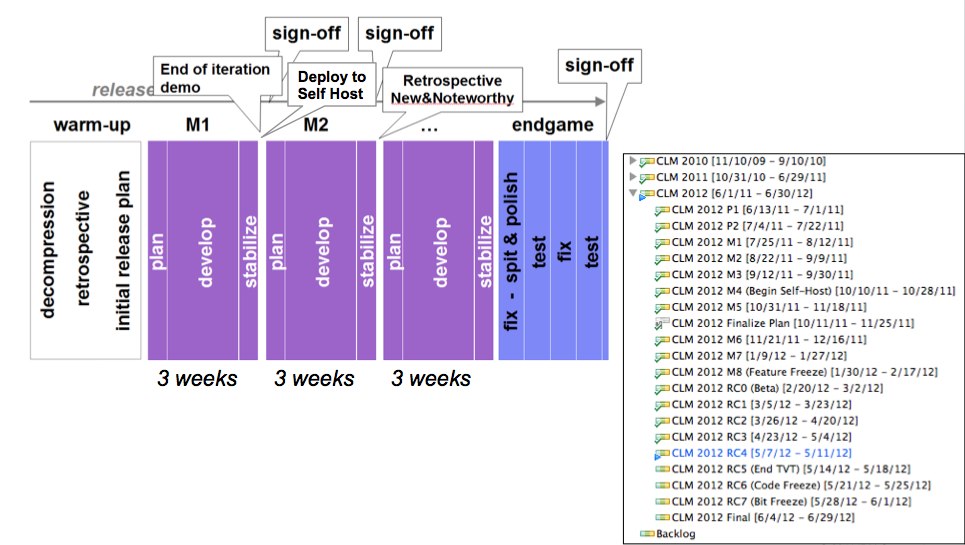
Figure 2. CLM 2012 Release Plan – links
The CLM Plan
The CLM Plan is used to define, manage, and track the cross CLM features being developed in a release. These are the features that cut across the solution and involved two or more of the products included in the solution. Products still have product unique features, but they only appear in the plan for the product. The CLM plan for 4.0 release is shown below in figure 3. Since this release is complete, most of the features have strike throughs, which is how the planning component shows completed workitems. Many of the figures in this article have a link above them to the actual artifact on jazz.net. You can click the link to go to jazz.net to explore the artifact in more detail.
For the CLM 4.0 effort, we used a release plan to define the overall release. The release plan was populated from the backlog at the beginning of the cycle. For CLM 4.0.1 and going forward, we have switched to a ranked backlog plan instead of a release plans and we take items from the top of the backlog at the beginning of each iteration. This change is to make the development organization more responsive to changing customer needs.
Take note of the 6th item in the ranked list shown below, “Support for changing the server public URL”. This is the plan item for the ability to change the URL of a CLM server. This was a major feature in the 4.0 release and involved extensive changes in all of the products that make up the CLM solution. We will use this particular feature as an example through much of the rest of this article.
CLM 2012 Release Plan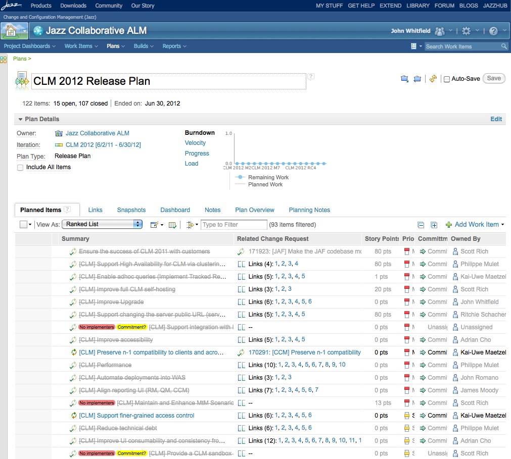
Figure 3. CLM 2012 Release Plan
Now lets look at the links tab in the release plan. This is where OSLC links to other related plans are shown. Looking at the “Tracks Plan” section you can see the links to the product specific plans for the products that make up the CLM solution. You can also see overall progress in terms of the number of story points planned versus implemented via the bar graphs to the right. In the “Tested by Test Plan” section, you can see the various test plans for testing at the CLM solution level. This includes both functional and system test plans. In the last section, “Implements Requirements Collection”, you can see the links to the set of requirements defined in RRC for the CLM solution.
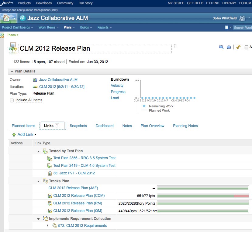
Figure 4. CLM 2012 Release Plan – links
One of the nice features of OSLC links is they support rich hovers. If you open the CLM plan on jazz.net and put your mouse over the link for the “CLM 2012 Release Plan (QM), you will see a hover window with a summary of that plan. If you click on the link you will navigate to that plan in your browser as shown below in figure 5. Note that you can use typical web browser functions such as right clicking and picking “open in window” or tab to control whether you navigate in the current browser window or open a new window or tab for the content.
In the QM plan, you can see all the features the RQM team is implementing for this release. This includes a mixture of functions that are QM specific as well as functions that are portions of a larger CLM feature such as Server Rename. The second item in the list below, “Data Reorganization (server rename)” is the QM plan item for supporting the CLM Server Rename capability. The 8th item in the list, “Improve process customization” is an example of an RQM specific feature.
RQM 2012 Release Plan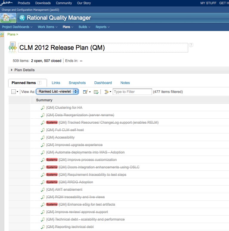
Figure 5. RQM 2012 Release Plan
The CLM plan also included links to test plans. If we click on the link “Jazz FVT – CLM 2012”, then you navigate to the functional verification test plan shown below in figure 6. This particular view shows the first 10 of the 214 test cases that make up the functional testing of the CLM solution.
CLM 2012 FVT Test Plan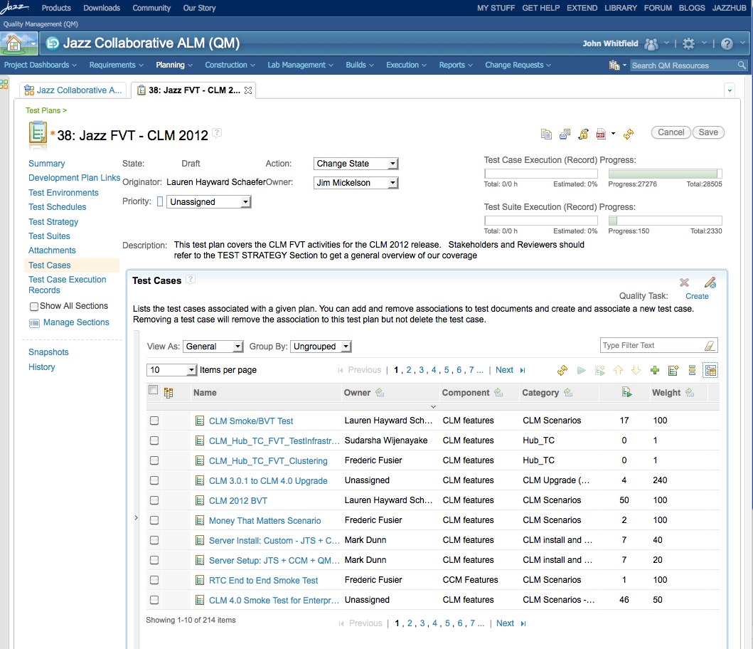
Figure 6. CLM 2012 FVT Test Plan
Example: Server Rename Feature
Now that we’ve seen how plans are organized at the CLM and product level, let’s look at how one of the CLM-wide features is organized. If you click on “Support for changing the server public URL” in the CLM plan, you will see the CLM level plan item for that feature as shown in figure 7 below. The plan item opens in the overview tab that includes general information such as who owns the item, its priority, when it’s targeted to be implemented, a description, and a discussion thread. You may also notice we’ve created customized tabs for our plan items which are unique to our development process. We will explore some of those tabs next. If you want to see other tabs, or explore in more detail, click the link above the diagram and you can explore this plan item in more detail on jazz.net.
CLM Server Rename Plan Item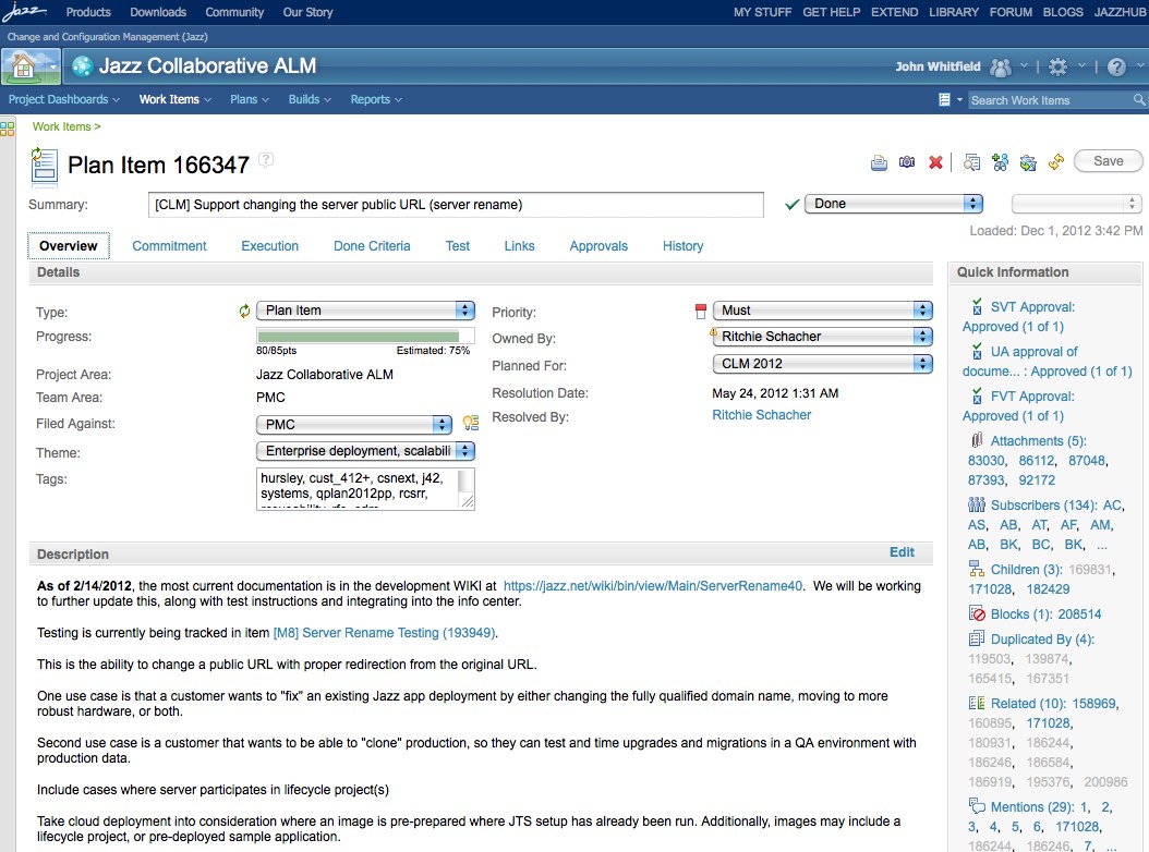
Figure 7. Server Rename CLM Plan Item
We use the “Execution” tab to track specific details on the development execution of this feature. One of the most important fields is the “Feature Team Lead”. We have found that in order to coordinate these important cross cutting features; we need a feature team lead working across the products. The feature team lead assembles a team of developers from each product to be responsible for the development of the cross cutting feature. The lead also holds scrum meetings with this team on a regular basis. The feature team members are typically the owners of the plan items for the product team’s work associated with this feature. The notes and status from the scrum meetings are recorded in the “weekly status” section of this tab. The tab also includes fields for the dev status and a roadmap for when the exploration, implementation, and testing are projected to be done.
CLM Server Rename Plan Item – Execution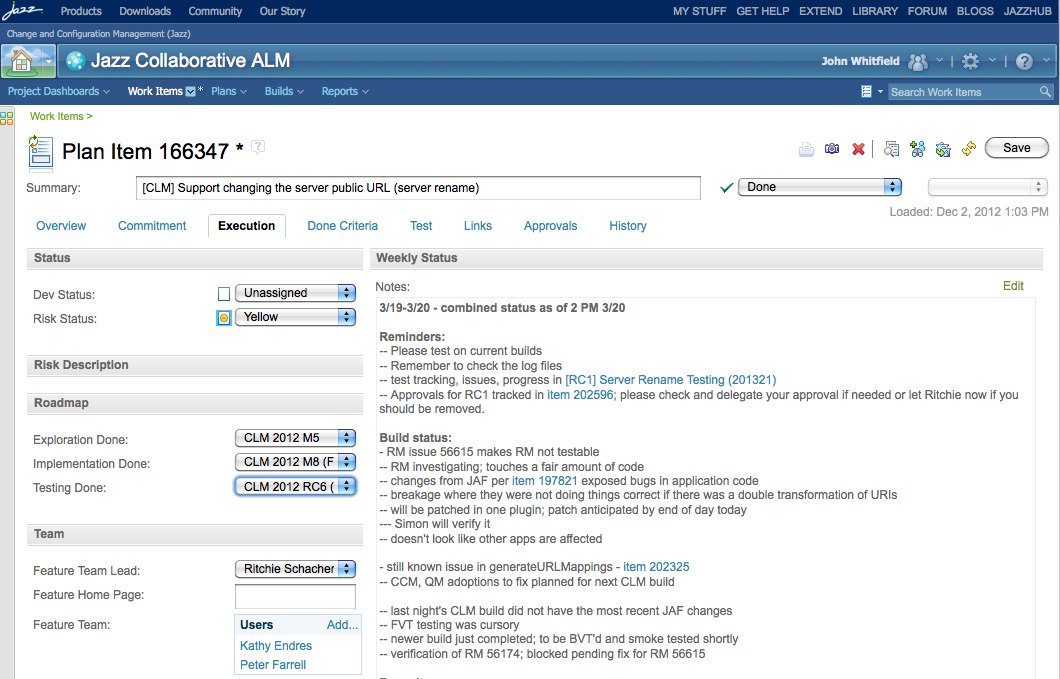
Figure 8. Server Rename CLM Plan Item – Execution
The “Done Criteria” tab is used to document what the end state for the feature looks like. This is created by the feature team and is used to know when they have achieved the goals of the feature. This is also useful for testing and can be used to design the test cases for the feature.
CLM Server Rename Plan Item – Done Criteria
Figure 9. Server Rename CLM Plan Item – Done Criteria
The “Test” tab is used to document whether testing has been committed for this feature and the test owner. It also includes whether the feature is tested via self-hosting. Testing “done criteria” and details of the testing coverage are also documented in this tab.
CLM Server Rename Plan Item – Test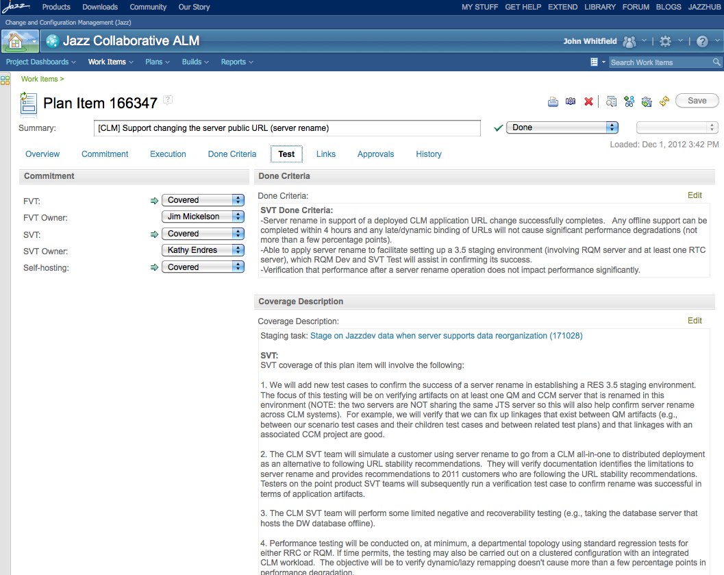
Figure 10. Server Rename CLM Plan Item – Test
As with the plans, the CLM level plan item for a feature is linked to the plan items in the product’s repository. The plan item local to the product defines and manages the product’s portion of the feature. This structure is shown in below in figure 11.

Figure 11. Plan Item Linking
The OSLC links are defined in the “links” tab and are organized by different link types. “Related Change Request” links are used to reference the plan items in the products included in the CLM solution. In figure 12 below, you can see that the CLM Server Rename plan item is linked to plan items in the Jazz Foundation, Rational Team Concert (CCM), Rational Quality Manager, and Rational Requirement Composer products.
CLM Server Rename Plan Item – Related Change Requests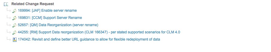
Figure 12. Server Rename CLM Plan Item – Related Change Requests
If you click on the “Data Reorganization (server rename)” link you will see the plan item shown below in the RQM project area.
RQM Server Rename Plan Item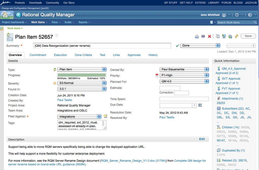
Figure 13. RQM Server Rename Plan Item
In addition to referencing the related plan items, the link tab of the CLM plan item also references the tests for the feature under the type “Tested by Test Case”. This is an especially important reference for teams using an agile process or for teams using a hybrid process consisting of both agile and traditional processes. Agile teams do not typically plan their testing in the form of a separate test plan. The ability to link test cases directly from the workitems gives the agile team the ability to use RQM to track and execute tests directly from workitems without having to create and maintain test plans. For teams with a hybrid process, that includes both agile and traditional processes, this structure lets both teams use the same test management tool. Agile development teams can track their tests through links from the workitems and traditional testers can still construct test plans that include their own unique test cases or include the test cases used in the agile testing.
CLM Server Rename Plan Item – Tested by Test Case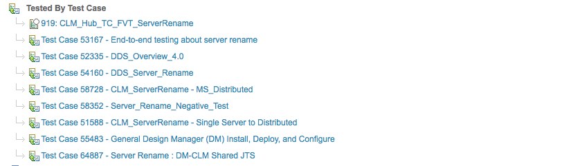
Figure 14. Server Rename CLM Plan Item – Tested by Test Case
If you click on the link “Test Case 58352 – Server_Rename_Negative_Test” then you see the test case shown below in the RQM web interface.
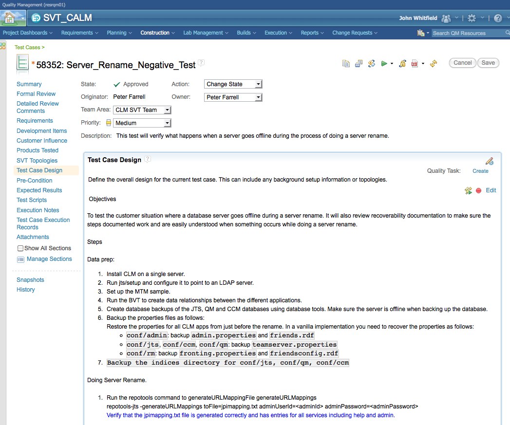
Figure 15. Server Rename Test Case
Finally, the “links” tab of the CLM plan item also includes references to the defects related to this feature under the “Affected by Defect” link type. This is a case where the OSLC rich hover is particularly useful since there can be a lot of defects. Hovers can be used to get a summary without navigating to a new page for each defect. Figure 16 below shows the links to defects in the Server Rename CLM plan item and shows the rich hover for one of the defects.
CLM Server Rename Plan Item – Affected by Defect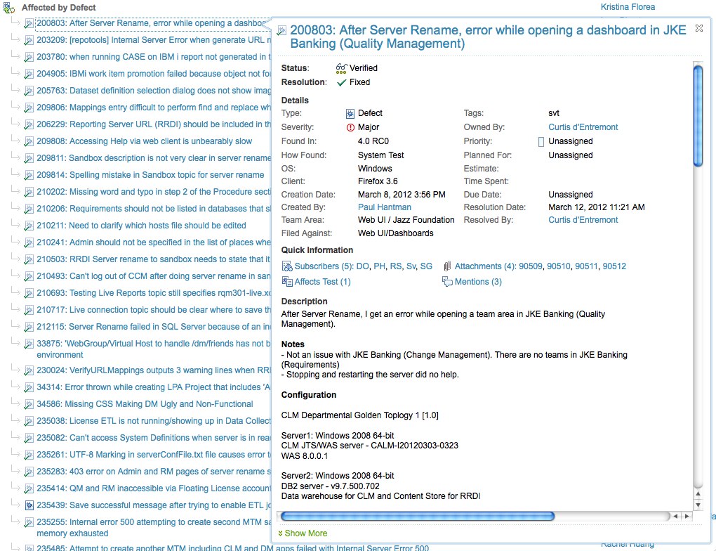
Figure 16. Server Rename CLM Plan Item – Affected by Defect
Once the CLM plan items have been decomposed into plan items within each of the product’s project area. Those plan items are broken down into stories and tasks to define and guide the specific development activities. The plan items in the specific product repositories also typically have links to test cases, requirements, and defects at the scope of the product in a fashion similar to what we’ve seen at the CLM solution level.
Track Build Item
Track Build Item (TBI) is a specific workitem type that plays a critical role in the development of the CLM solution. They are used to track the continuous build process for the scope of an iteration. We create a TBI for each iteration and the team leads and managers for all involved components are subscribed as shown in figure 17. The discussion in the TBI is a key communication vehicle across the team for keeping the complex build process associated with the overall CLM solution running. A snippet of TBI discussion is shown in figure 18. If you want to see more details on the typical discussion in a TBI, click the link above figure 17. You will see that the discussions in a TBI are typically very active and detailed. You will likely see references to CLM Blocker defects in the TBI discussion. We tag any defect that blocks the continuous build process or breaks our automated build verification tests with the clm_blocker tag. These defects are treated as very high priority and are discussed in the daily scrum for the CLM solution.
Track Build Item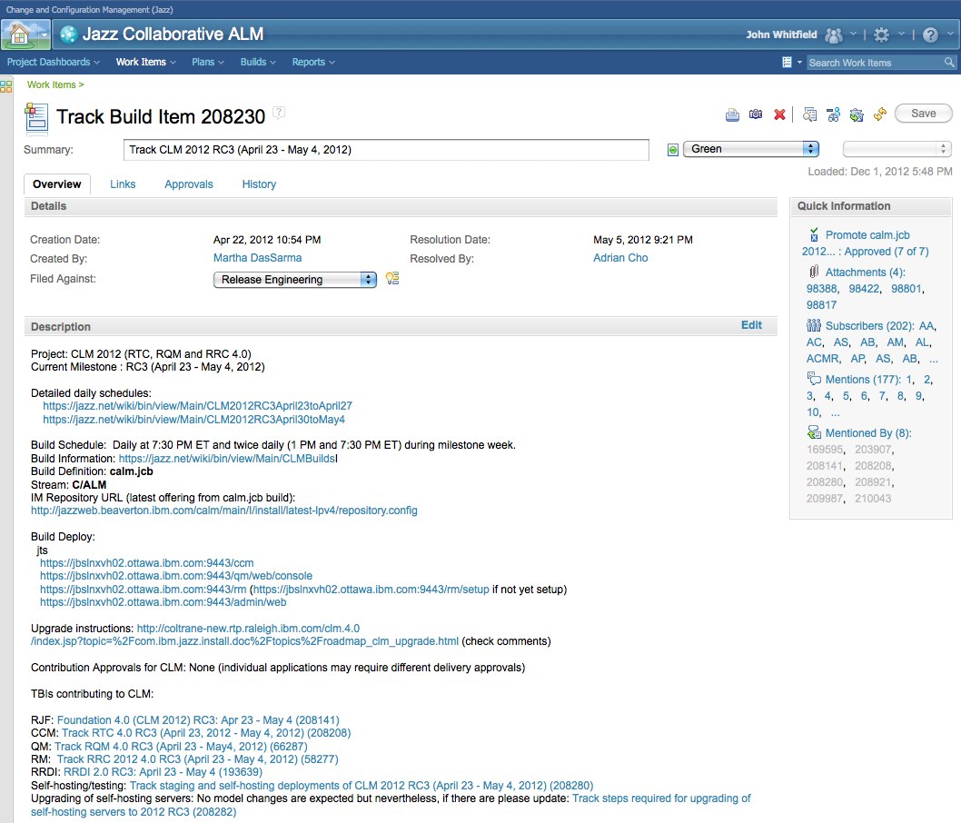
Figure 17. Track Build Item
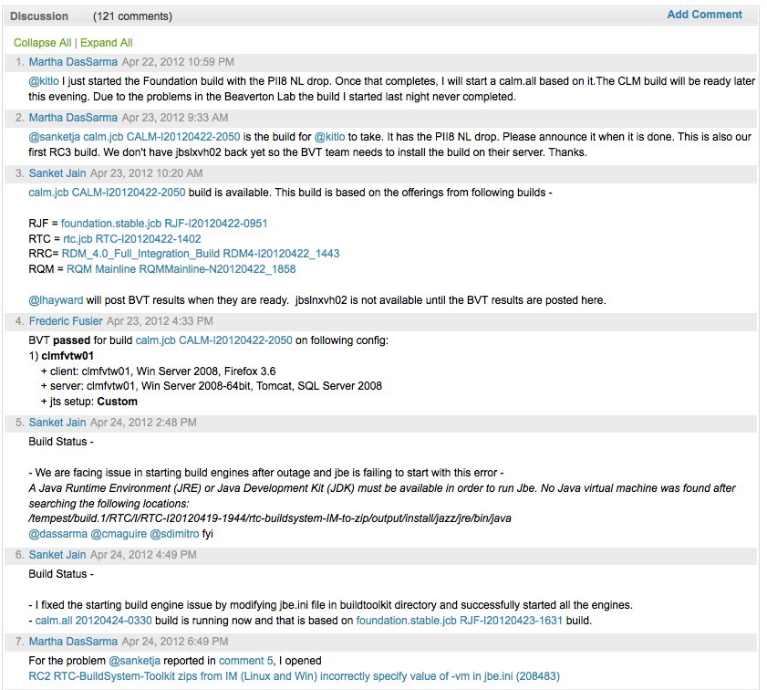
Figure 18. Track Build Item – Discussion
Tracking Status with Dashboards
Dashboards are the primary status tracking mechanism for the CLM solution development organization. The general tab shown in figure 19 includes basic information about the CLM solution such as the currently active TBIs, overall plan status, and key milestone dates. We will examine a few of the tabs in this article, but more detail is available by clicking the link and examining the dashboard on jazz.net.
CLM Dashboard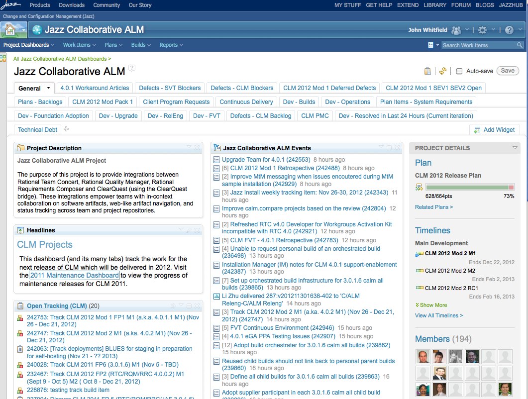
Figure 19. CLM Dashboard
The CLM Blockers tab is one of the most used tabs and lists the defects for each product team with a clm_blocker tag. This is the tab that is used in the CLM daily scrum to discuss progress on blocking defects.
CLM Dashboard – CLM Blockers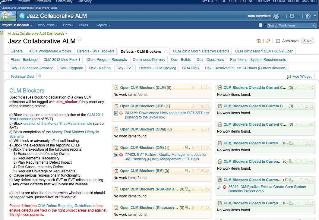
Figure 20. CLM Dashboard – CLM Blockers
There are also feature team dashboards for the key cross cutting CLM features. Figure 21 below shows the dashboard for the server rename feature team. It tracks the active defects that impact this specific CLM feature. This dashboard is used during the feature team’s scrum meeting to guide the defect status discussion.
CLM Dashboard – Server Rename Feature Team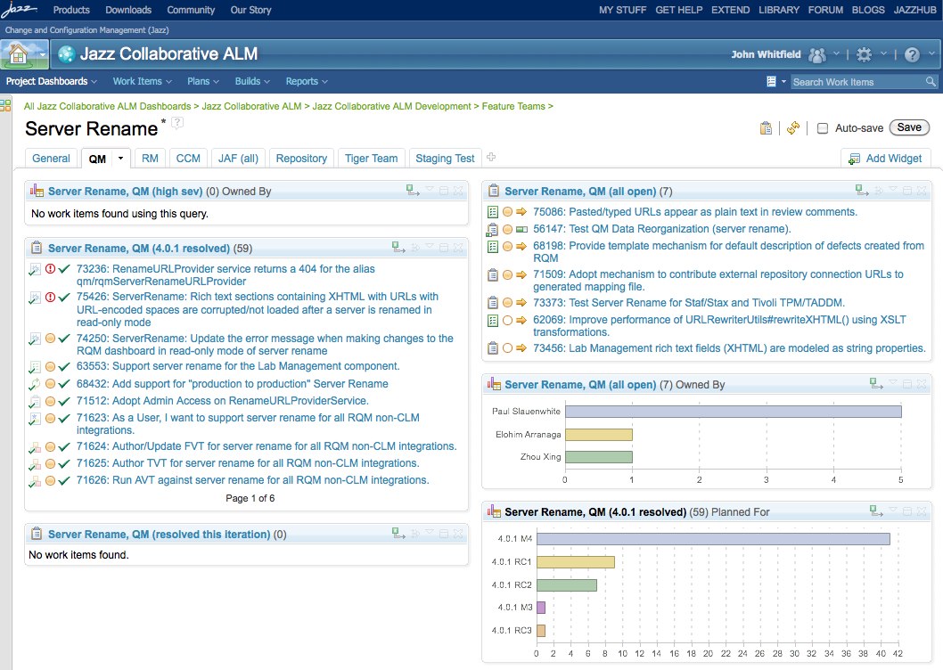
Figure 21. CLM Dashboard – Server Rename Feature Team
About the author
John Whitfield is the architect for the Rational Quality Management business segment and is responsible for Rational Quality Manager, Rational Performance Tester, Rational Functional Tester and the newly acquired Green Hat products. He is an expert in best practices and usage models for test management and spends a great deal of time working with customers on the usage and adoption of Rational Quality Manager. He can be contacted at jpwhit@us.ibm.com.
Copyright © 2012 IBM Corporation